ESPHome AUX AC Controller PCB: Build Log from Rev 00 to Rev 01
Table of contents
This is the complete story of board 3104, a small ESPHome controller for AUX air conditioners. It started as one post per milestone; this page puts the whole build log in one place, from the first schematic to the second production lot, including the parts that went wrong.
What the board does
AUX air conditioners talk to their Wi-Fi module over a UART. The open-source ESPHome AUX AC component by GrKoR speaks that protocol, so an ESP32 running ESPHome can replace the stock module and put the AC into Home Assistant: temperatures, mode, fan speed, swing and presets.
The component needs hardware to run on. Board 3104 is that hardware: a 2-layer PCB with its own power supply and an ESP32-S3-WROOM-1, powered from the AC unit's internal bus. Full documentation (schematic, PCB, PCBA renders and a simple ESPHome configuration) is in the 3104 repository on GitLab.
Revision 00: the design
The schematic was drawn in KiCad and is deliberately simple:
- 5-pin 2.54 mm connector to the AC
- reverse polarity (RP) diode
- switch-mode power supply built on a TPS562203 buck converter
- ESP32-S3-WROOM-1
- a button for BOOT selection
- series resistors on the UART lines for protection
The PCB:
- 2 layers, 1.6 mm thick
- 25 × 50 mm (plus connector overhang)
- components on one side only
Renders of the assembled board: PCBA top and PCBA bottom.


Connector pinout (rev 00): ESP TX, ESP RX, NC, GND, +SUP.
Design limits:
- supply voltage from 4.8 V to 17 V
- reverse polarity protection down to −30 V
Revision 00 arrives – and fails (a bit)
31 October 2024. The first batch of 3104-00 PCBAs arrived. The basic bring-up went well:
- supplying it with 5 V didn't damage anything
- the regulator output was stable at 3.3 V
- the ESP32 could be programmed over UART, and after that over Wi-Fi
Then the real test: connecting it to the air conditioner. That passed too – the board talked to the AC. But two mistakes showed up as soon as the board met the real cable:
- Wrong connector pitch. I had picked a 2.54 mm connector; the AC side uses 2.00 mm.
- TX and RX swapped. The pinout was assigned the wrong way round, so the UART lines did not line up with the AC's.
Neither is exotic. Both are the kind of error that a schematic check against the mating connector's datasheet, and a second look at "whose TX is this?", would have caught before ordering. They still cost a full board revision.
Revision 01: the fixes
26 November 2024. Revision 01 fixes both problems and adds two improvements:
- connector replaced with a 2 mm pitch part
- TX and RX swapped to match the AC
- a voltage divider population option on the ESP RX pin, for extra RX pin protection
- connector rotated by 90° so the cable is easier to plug in
Revision 01 arrives
18 December 2024. The first batch of 3104-01 PCBAs arrived, with a black matte soldermask that looks great (at least in my opinion).
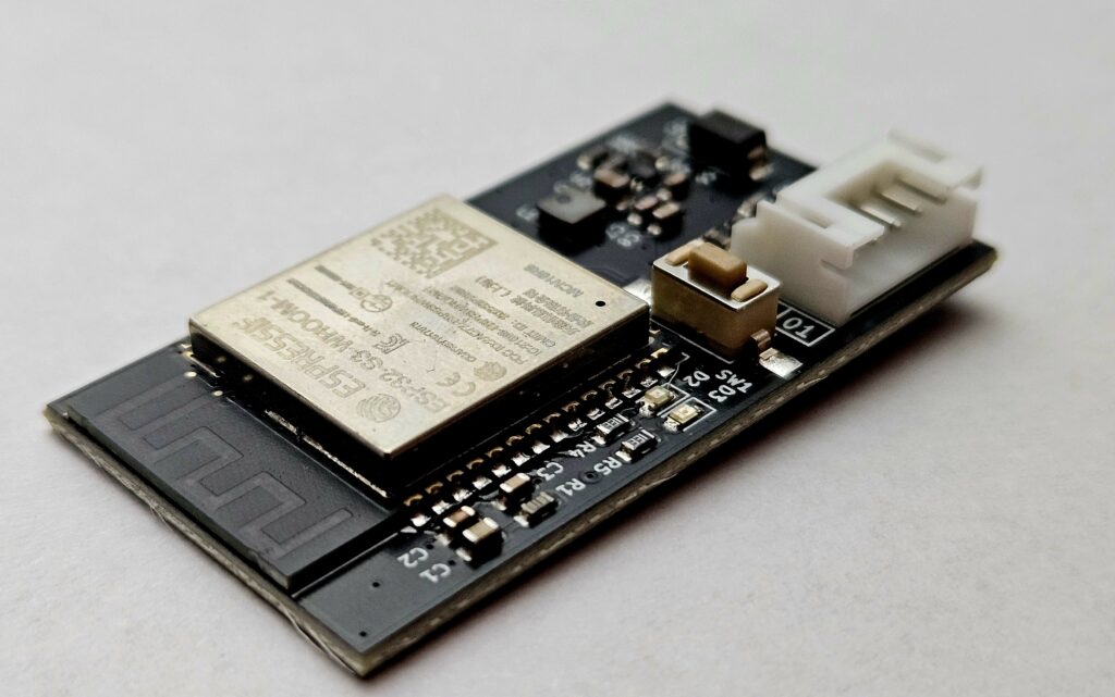
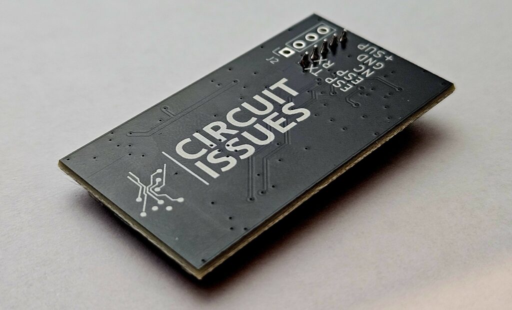
The same bring-up as rev 00, plus the step that failed last time:
- 5 V supply: no damage
- regulator output stable at 3.3 V
- programming over UART, then over Wi-Fi
- communication with the AUX AC unit tested and working
- the GitLab documentation updated with a simple configuration
The final revision ended up 25 × 46 mm.
What I'd tell anyone building something similar
- Check the connector against the mating part, not just the footprint library. Pitch is easy to get wrong and impossible to fix with a bodge wire.
- Name UART nets from one side's point of view (for example
ESP_TX,ESP_RX) and write down which pin the other side transmits on. - Leave a population option for level shifting on any input that comes from equipment you don't control.
- Bring up in order – power, programming, then the real interface – and log every step. That's why this log exists.
Getting the board
The 3104-01 is now available ready to use, pre-flashed with ESPHome: see the ESPHome AUX AC PCBA product page. The same TPS562203 power stage is available as a KiCad design block, the TPS562203 buck converter block, alongside an ESP32-S3 core block (WROOM-2 based) in the template library.
Designing your own board and want a second pair of eyes before you order? The Hardware Clinic pre-fab check exists for exactly the kind of mistakes described above. Questions about this board: contact@circuit-issues.com or the contact form.