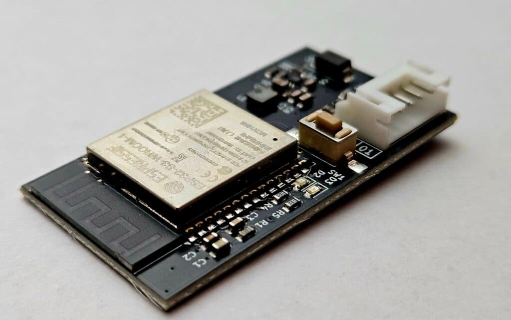
Flossa AI Controller: a Battery-Powered ESP32-S3 Audio Board Built from Template Blocks
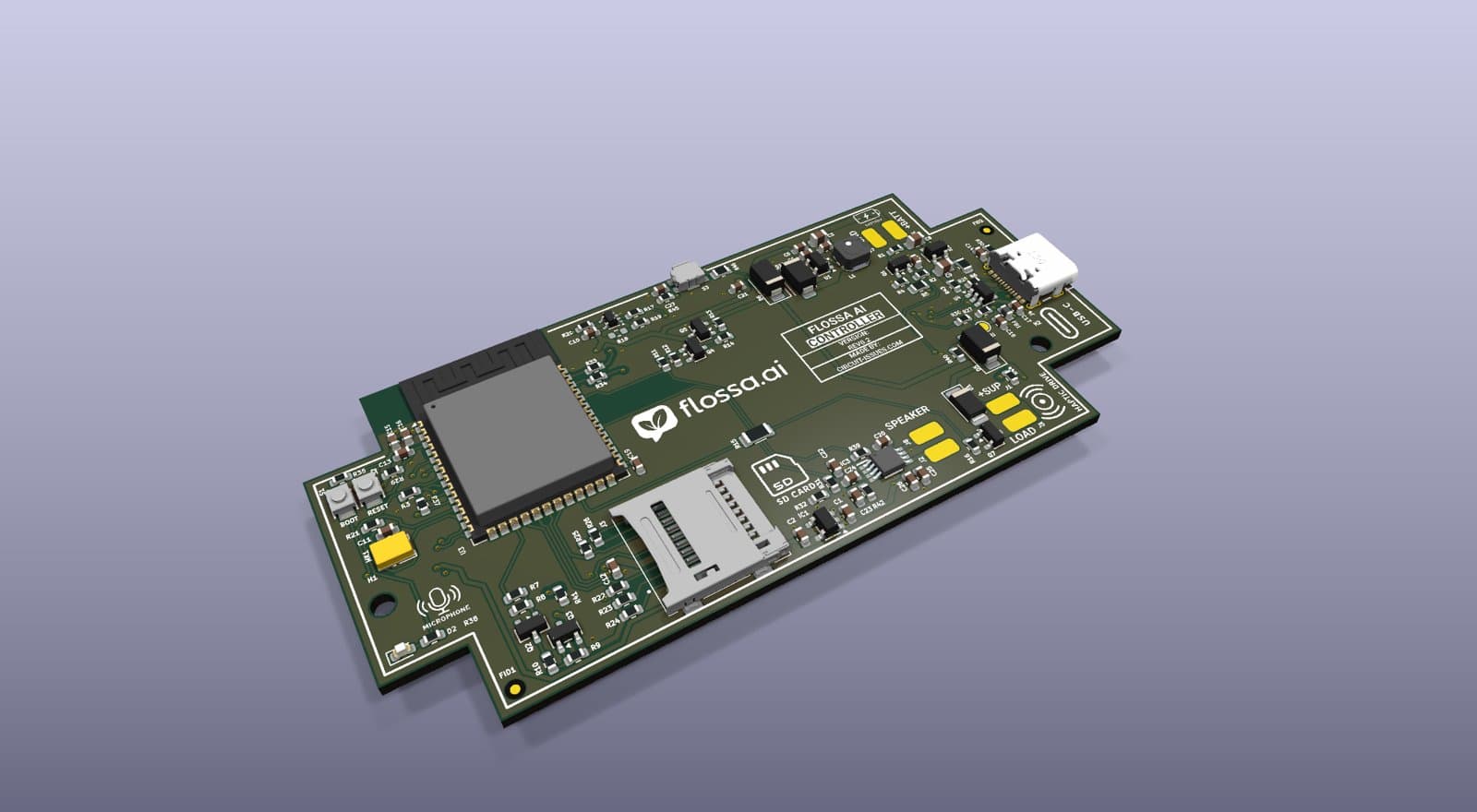
Table of contents
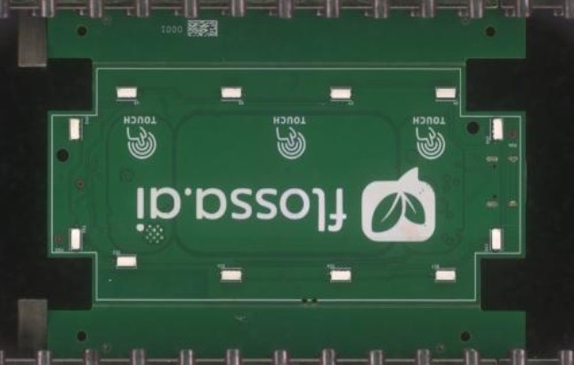
flossa.ai needed a compact controller that listens, talks back, stores data locally and runs from a battery. Instead of designing every subsystem from scratch, we assembled the board from our own proven KiCad template blocks. Only the LED ring and the touch area on the back were drawn by hand.
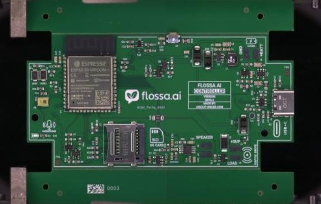
The result is the Flossa AI Controller, revision REV0.2: a 4-layer, 96 × 46 mm board with 114 components, built from 10 template blocks (11 instances) plus one custom sheet.
What is on the board
| Block | What it does on this board |
|---|---|
| 0140 ESP32-S3 core, WROOM-2 | ESP32-S3-WROOM-2 (N16R8V) with USB-C programming and USBLC6 ESD protection. Runs audio, storage, LEDs and power management. |
| 0125 Li-Ion / LiPo charger 4.2 V (MCP73832T) | Charges the battery from USB-C and reports charge state and battery voltage to the MCU. |
| 0105 Boost converter battery → 5 V (TPS613222A) | Steps the battery up to a stable 5 V rail for the amplifier and LEDs. |
| 0090 Low-Iq LDO 5 V → 3.3 V (RT9080-33GJ5) | Low quiescent-current 3.3 V logic rail for long battery standby. |
| 0115 High-side switch 3 A (AO3401A + AO3400A) × 2 | Gates the 3.3 V and 5 V peripheral domains so they are fully off when idle. |
| 0030 MEMS microphone, PDM (IM72D128V01) | Digital PDM microphone wired directly to the ESP32-S3 PDM input. |
| 0150 Class-D amplifier 2.5 W mono (PAM8302A) | Drives the speaker from the MCU audio output, with shutdown control. |
| 0200 microSD card holder, SPI | Local storage over SPI. |
| 0110 Low-side switch 5 A, 24 V | PWM drive for the haptic feedback motor. |
| 0040 Level translator 3.3 V → 5 V (74AHCT1G125) | Shifts the LED data line up to 5 V logic for the addressable LEDs. |
The core block was adapted for this product with B3U-1000P BOOT/RESET buttons and an extra right-angle button on the supply line.
How the blocks fit together
One battery power path, three blocks. USB-C feeds the 0125 charger, the battery feeds the 0105 boost to 5 V, and the 0090 LDO derives 3.3 V. Each block came with its own layout rules, so the power path needed no extra design work.
Power domains switched off when idle. Two 0115 high-side switches let firmware cut the 3.3 V and 5 V peripheral rails. The same block is placed twice, with only the sheet ID changed.
Audio in and out with no glue logic. The 0030 PDM microphone and the 0150 amplifier connect straight to the 0140 core pins. The interfaces match because the blocks share naming and pin conventions.
Custom only where the product needs it. The 12 addressable RGB LEDs and three touch pads on the back follow the product enclosure, so they were drawn for this board. The 0040 level translator still handles the 3.3 V → 5 V LED data.
How it went
We went from idea to an assembled controller remarkably fast. Because the board was built from proven blocks, everything worked from the first power-on: audio, charging, storage and LEDs, with no rework on the first revision.
— Flossa team
The full showcase, with 3D renders and every block linked to its template, is on the Flossa AI Controller showcase page. If you want a board like this for your own product, the blocks are in the template library, and the Hardware Clinic reviews a finished design before you order boards.