UART level translator 3.3 V ↔ 5 V
Two-channel UART level translator between a 3.3 V microcontroller and a 5 V device (or any two logic levels from 2 to 5.5 V): one buffer per direction, each powered from the side it drives, with TTL-level, 5.5 V-tolerant inputs. Series resistors on every input and output limit fault currents and ringing. Used as the 5 V UART side of the heat-pump / AC link.
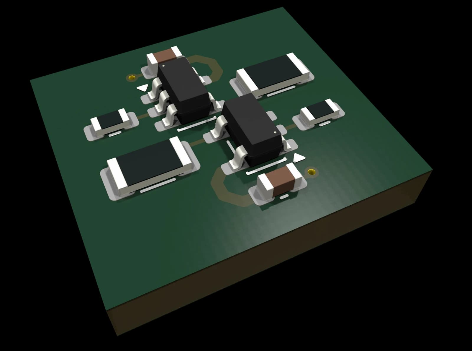
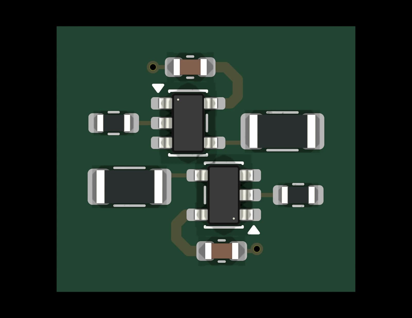
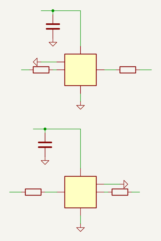
Key specifications
- Two independent supplies, 2–5.5 V each
- One channel each way: MCU TX → device RX, device TX → MCU RX
- 5.5 V-tolerant inputs, push-pull outputs
- UART speeds well above 1 Mbit/s
Design notes
- Push-pull, one direction per line: for UART and other one-way signals, not for I²C.
This block is not available yet. It is released once its checks are complete. Planned price: €29.
Planned package contents
KiCad 10 design block
Schematic and PCB layout fragment; symbols and footprints embedded
BOM (CSV)
Manufacturer part numbers and LCSC codes
Schematic PDF + README
Interface, specs, population options and design notes
3D models
STEP models of the special parts; standard parts use KiCad’s 3D library
template.yaml
Machine-readable interface and limits
PCB Composer
Get blocks like this one composed and routed into one board for your device, without opening KiCad. Quote within 24 h.
About PCB ComposerDevelopment status
| Block ID | 0165 |
|---|---|
| Block name | 0165-uart-level-translator-3v3-5v |
| Version | 1.0 |
| Status | DRC clean – Schematic and layout pass the KiCad rule checks; not yet verified on hardware. |
| Open review items | 4 (0 blocking) |
| PCB layout | Rule-checked layout fragment |
| Format | KiCad 10 design block (schematic + PCB) |
| Last change | 2026-11-03 |
Interface
Hierarchical labels the block exposes to the rest of your design.
| Net | Direction | Description |
|---|---|---|
| +BUF_IN_SUP | Power in | Supply of the MCU side (e.g. 3.3 V) |
| +BUF_OUT_SUP | Power in | Supply of the device side (e.g. 5 V) |
| BUF_OUT_DO | Input | From the MCU UART TX |
| BUF_OUT | Output | To the device RX, at the device-side level |
| BUF_IN | Input | From the device TX, up to 5.5 V |
| BUF_IN_DI | Output | To the MCU UART RX, at the MCU-side level |
FAQ
Which KiCad version do I need?
KiCad 10. The files are saved in the KiCad 10 format and are meant to be placed with KiCad’s Design Blocks feature (schematic block, then “Apply Design Block Layout” on the PCB).
Do I need the Circuit Issues part library?
No. Symbols are embedded in the schematic and footprints in the PCB, so the block opens on its own. Parts carry manufacturer part numbers and LCSC codes.
Is the layout production-ready?
The layout fragment passes the KiCad design rule check. Route it into your board and run DRC with your own fab rules.
Can I use the template in a commercial product?
The licence terms are published together with the first release.
Related templates
0160 RS-485 Transceiver 3.3 V
KiCad 10 design block: half-duplex RS-485 / Modbus RTU port for a 3.3 V UART with TVS protection, fail-safe bias and a termination jumper.
DRC clean0140 ESP32-S3 Core (WROOM-2)
Free KiCad 10 design block: ESP32-S3-WROOM-2 (16 MB flash, 8 MB PSRAM) with native USB-C, ESD protection, BOOT/RESET buttons and 22 GPIOs on labels.
DRC clean0101 Buck Converter 2 A
KiCad 10 design block: synchronous buck converter, 4.5–17 V in, 3.3 V / 2 A out (5 V option), with optional reverse-polarity diode.
DRC clean